Preface
Finally, it’s the end of this semester. We’ve learned a lot of 8051 assembly code programming from this course, including simple I/Os, interrupts, timers, UART, etc. This time, we are trying to improving our 8051 coding skill to next level. Therefore, “Remote Control Car” becomes our challenge for the final project. We got to bring out the coolest toy car!
Abstraction
They are 4 DC motors, which drives the car forward, backward, turn left, and turn right, on the remote controlled car we designed. Our main chip, 8051, receives the signals from Bluetooth UART module, and control those motors by NPN transistors and relays. It turns out that we can control the car via Bluetooth on our laptop.
Development Flowchart
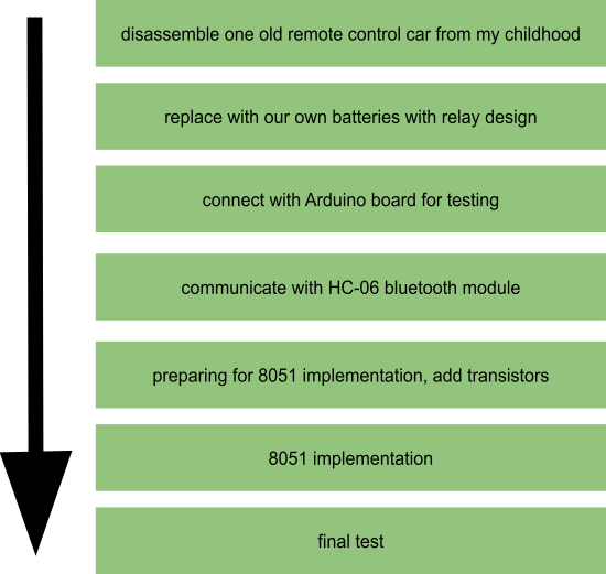
In the other words, we tried to rebuild the remote control car by using Arduino Duemilanove with HC-06 Bluetooth module first. Then, added transistors before the implementation on 8051.
Components
Before we get started, I would like to list out the components we are using in this project.
89S51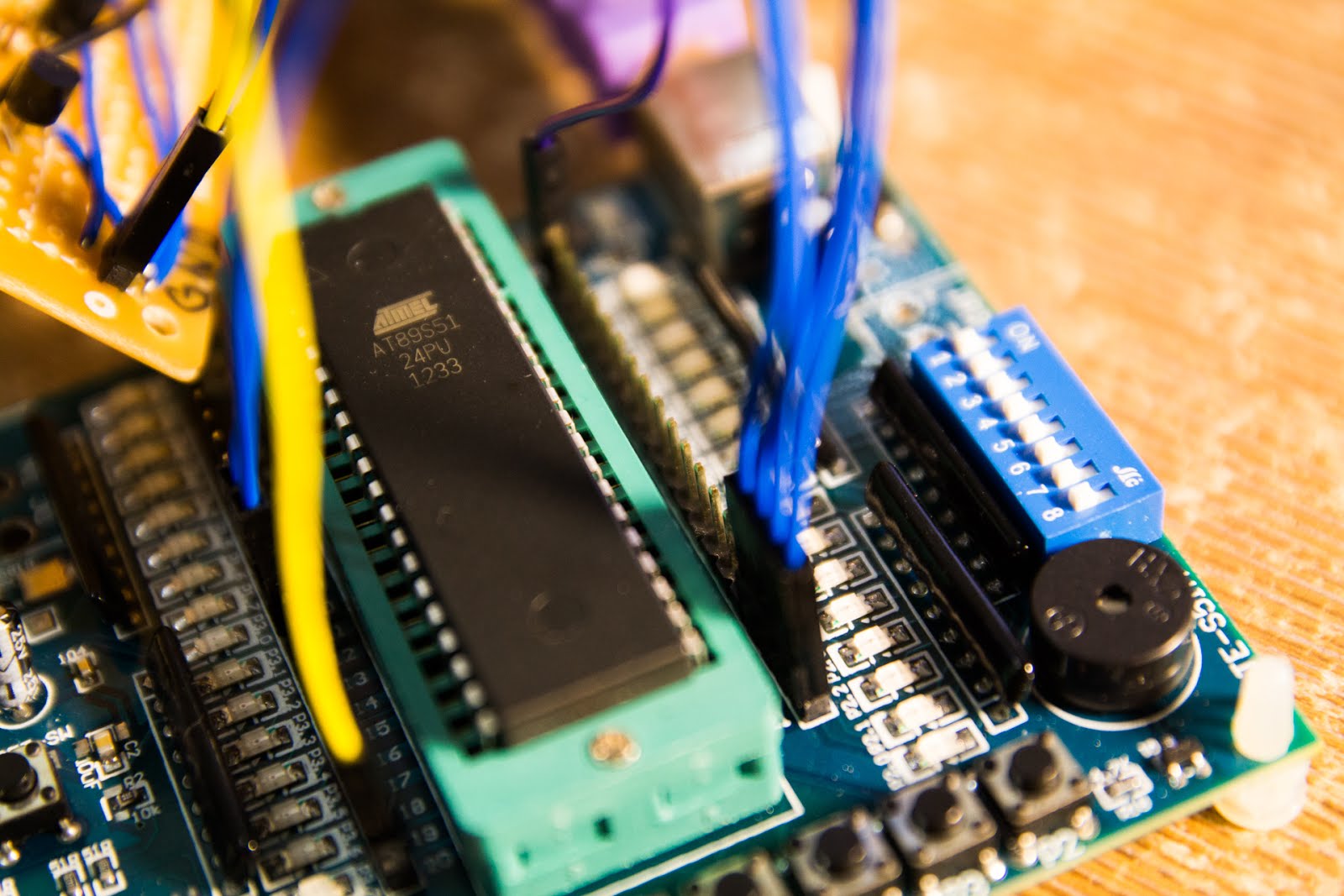
What’s the difference between 89S51 and 89C51?
The biggest difference is that 89S51 is offering ISP feature. “ISP” is the ability of some programmable logic devices, microcontrollers, and other embedded devices to be programmed while installed in a complete system, rather than requiring the chip to be programmed prior to installing it into the system (quote from Wikipedia).
That means that we can program the chip without other tools but simple serial port instead. And, it’s not only more convenient but also cheaper.
Why 89S51 instead of 89C51?
Since the remote control car need a place for it to drive around and a longer developing time, we think it will be better if we develop in our own place. To setup an environment for 8051 developing, we first have to find out a way to burn our code into the 8051 chip in our own place. Here are the solutions we had before we get started:
Solution
|
Advantage
|
Disadvantage
|
Use ICE Emulator in EC222
|
No extra equipment.
|
Not able to put on our car and EC222 doesn’t offer flexible open hours.
|
Use 89S51 & use ISP to burn the program
|
Able to develop in our own place.
|
We have to buy extra experiment board.
|
Since 89S51 offers ISP feature, it’s much easier for us to write code on it instead of using ICE Emulator.
What’s our developing environment if using 89S51?
We are using “TE-S51A” experiment board this time. It’s much cheaper than buying the ICE emulator, and it offers a simple ISP burner which save our time to build our own ISP driver. TE-S51A is connected with the laptop via USB cable, which is simple.
Motors and Batteries
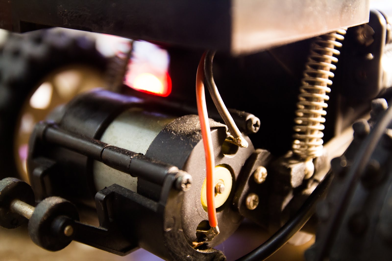
4 DC motors are applied in this project. Each of them requires at least 3V power supply. Therefore, we’ve wired each of them up with one pair of batteries. DC motors have a simple mechanical design, but they are powerful for moving the car fast.
Usage
|
Motor
|
Required Input Voltage
|
Forward
|
Back Motor
|
3V
|
Backward
|
Back Motor
|
3V
|
Turn Left
|
Front Motor
|
3V
|
Turn Right
|
Front Motor
|
3V
|
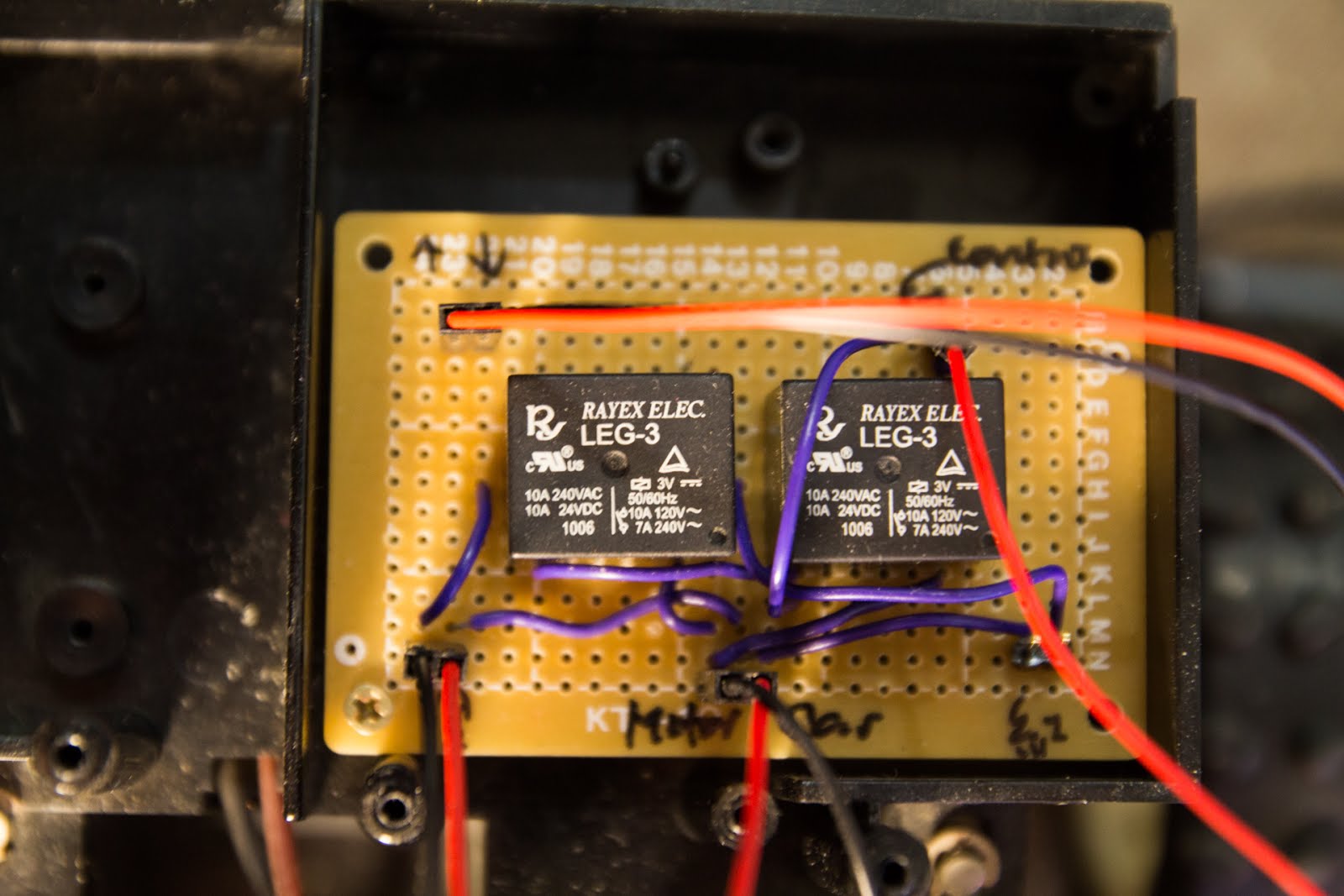
Relays
The motor are using high-current circuits, but the circuit for 8051/Arduino is not. These two kinds of circuits should be separated to avoid conflicts. Relays total solve this problem here. See one of our circuit design here: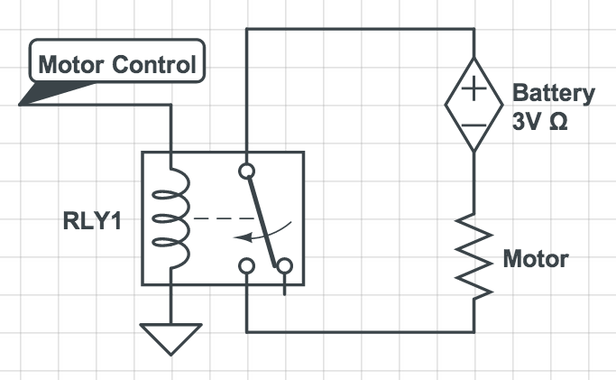
The “Motor Control” wire can be set by the controller (8051 or Arduino); if it’s set, the motor will start to work. We apply this design for all the motors, so we need 4 pairs of batteries and 4 relays in total.
NPN Transistors
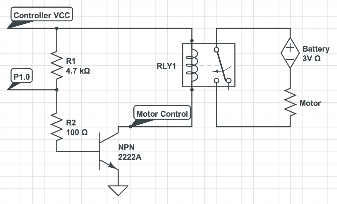
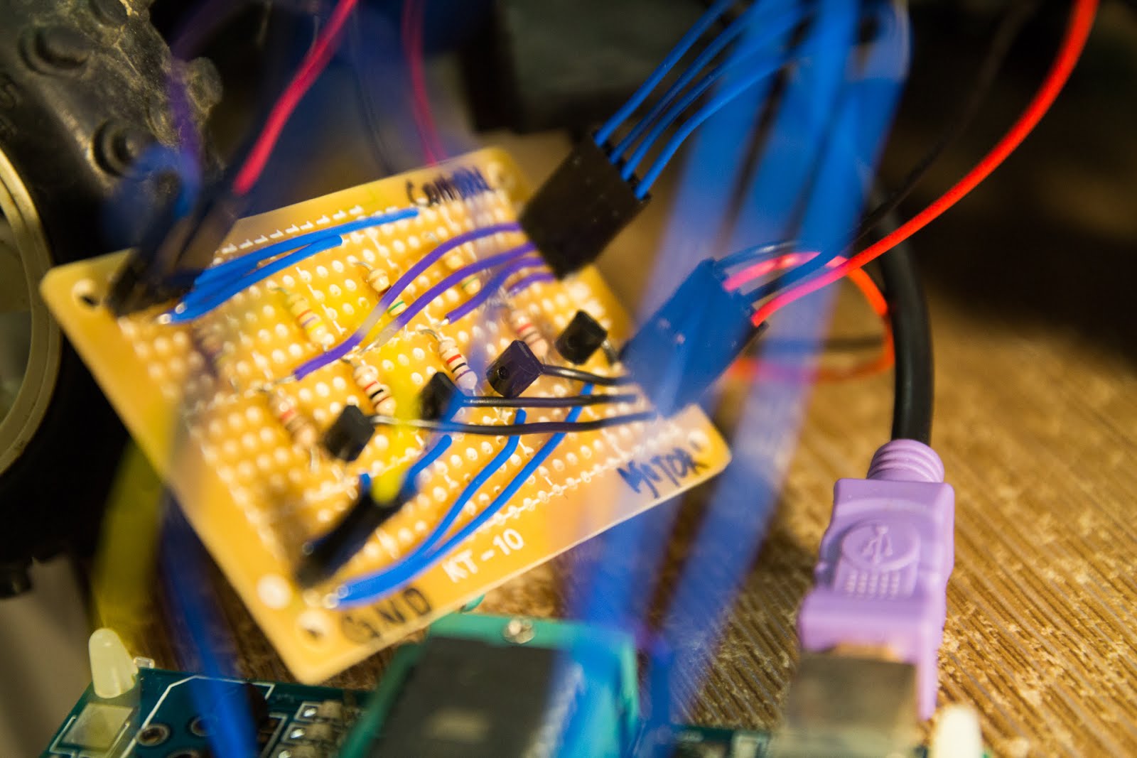
When we start to use 8051 instead Arduino, we found that they don’t have the same behavior. In Arduino, we can simply pull up one of the pin, and switch on the relay, but it’s different when I work on 8051. I pull up one of the pin on 8051 and checked it’s around 4.5V; however, when my relay is connected, it comes to around 0V. This tells me that 8051 is not offering enough current to the relay, and it’s not able to switch on the relay.
To solve this problem, we added “NPN transistors”. By using the transistors, only small current is needed to turn on the relay.
Bluetooth Module (HC-06)
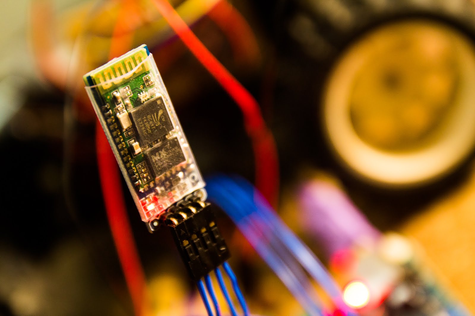
In order to build a “wireless” remote car, we decided to use bluetooth to communicate with our laptop. It’s advantage is light and cheap, and disadvantage is that the time for pairing take a little long.
Using the Bluetooth module HC-06 is pretty simple. There are only four pins on it as below:
VCC
|
Working Voltage ~= 5V
|
GND
|
Ground
|
RX
|
UART Receive Port
|
TX
|
UART Transfer Port
|
And this is how we connect HC-06 with our 8051.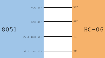
Arduino Duemilanove
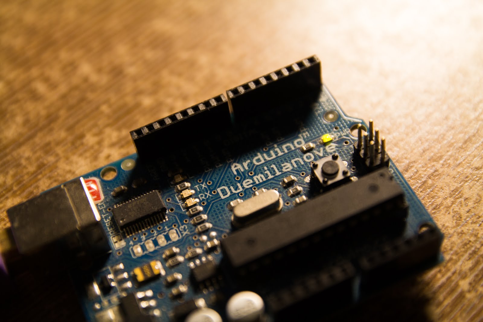
Before we got our hand dirty on 8051, we first used Arduino for testing. Arduino offers much better platform for developers, and we can test our circuit designs in a short time. However, it seems that this board is not desired in our lab, so we have to switch back to 8051 after our testing.
System Structure
System Flowchart
By combining all the components, we can build up our remote control car. The signal flowchart of the whole system can be learned from the following graph.
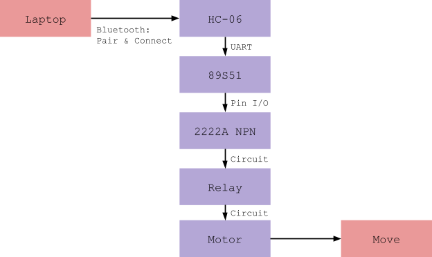
There are four types of signals for controlling the car in order to give different commands for the car.
Signal Name
|
8051: UART Input
|
Arduino: UART Input
|
Forward
|
arrow up
|
‘w’
|
Backward
|
arrow down
|
‘s’
|
Turn Left
|
arrow left
|
‘a’
|
Turn Right
|
arrow right
|
‘d’
|
8051/Arduino have different reaction on different signals, and actually the code is quite simple.
ASM code for 8051
MOV TMOD, #20H
MOV TH1, #-3 ; 9600 baud
MOV SCON, #50H
SETB TR1
MOV P2, #00000000b
HERE: JNB RI, HERE;
MOV A, SBUF
; A is the input char
CJNE A, #01000001b, NOT_CASE1
ACALL FORWARD
JMP CONTINUE
NOT_CASE1:
CJNE A, #01000010b, NOT_CASE2
ACALL BACKWARD
JMP CONTINUE
NOT_CASE2:
CJNE A, #01000100b, NOT_CASE3
ACALL LEFT
JMP CONTINUE
NOT_CASE3:
CJNE A, #01000011b, ELSE_CASE
ACALL RIGHT
JMP CONTINUE
ELSE_CASE:
ACALL CLEAR
CONTINUE:
CLR RI
SJMP HERE
;
CLEAR:
MOV P2, #00000000b
RET
FORWARD:
MOV P2, #00000001b
RET
BACKWARD:
MOV P2, #00000010b
RET
LEFT:
MOV P2, #00000100b
RET
RIGHT:
MOV P2, #00001000b
RET
END
C code for Arduino
char INBYTE;
char GO_IN = 'w';
char BACK_IN = 's';
char LEFT_IN = 'a';
char RIGHT_IN = 'd';
int GO_PIN = 12;
int BACK_PIN = 11;
int LEFT_PIN = 10;
int RIGHT_PIN = 9;
void setup() {
Serial.begin(9600);
pinMode(LED, OUTPUT);
pinMode(GO_PIN, OUTPUT);
pinMode(BACK_PIN, OUTPUT);
pinMode(LEFT_PIN, OUTPUT);
pinMode(RIGHT_PIN, OUTPUT);
}
void loop() {
while (!Serial.available()); // stay here so long as COM port is empty
INBYTE = Serial.read(); // read next available byte
if( INBYTE == GO_IN )
digitalWrite(GO_PIN, HIGH);
else
digitalWrite(GO_PIN, LOW);
if( INBYTE == BACK_IN )
digitalWrite(BACK_PIN, HIGH);
else
digitalWrite(BACK_PIN, LOW);
if( INBYTE == LEFT_IN )
digitalWrite(LEFT_PIN, HIGH);
else
digitalWrite(LEFT_PIN, LOW);
if( INBYTE == RIGHT_IN )
digitalWrite(RIGHT_PIN, HIGH);
else
digitalWrite(RIGHT_PIN, LOW);
delay(50);
}
Further Challenges
We’ve finally built our own remote control car using Bluetooth on 8051. However, we think that it’s is not stable enough at this point. And, we also believe that there’s more possibilities behind this project.
Not Stable Enough
Since we are building almost everythings on our own, including soldering the wires, circuit designs, and the assembly code. Some of them don’t always give out a stable work. The car will stop working if one of the problems occurs. Here, I am listing some of them out:
Wires don’t connect well.
Motor is blocked by other stuffs since there’s too much things on the car.
Batteries are out of charge.
More Improvements
Here are some improvements we can think of, and hope that we can continue on these in the future.
Video Streaming: Actually, we’ve put one cell phone on the car, and streamed the video back using Skype, so users can see the view from the current when operating it.
Mobile App Integration: Another reason for using Bluetooth instead of IR is that we can write an app to control the car in the future. People are playing car racing game on mobile phones, and we want to make the same thing but the car in the game is real. What’s more, we believe that using G-sensor, which is already embedded in our smart phones, is a better way to control the car.

